A year or so ago when I started my yourney into embedded development (to build a PID controller for my coffee machine) I bought a 1.5 inch RGB OLED display, which uses a SSD1351 controller. I got lucky, because a display driver for it already existed.
Unfortunately, very recently it stopped working and I’m not sure why. Okay, maybe I tightened those screws a bit too much. Anyways, since I did not need a color display, I bought a very similar 1.5 inch OLED display. After plugging it in and not seeing anything rendered on the screen (and not touching my screwdriver), I realized that it uses a different controller: the SSD1327. This time I wasn’t as lucky, because there happened to be no embedded rust driver out there yet.
When life gives you lemons, write a display driver for them - and then blog about it so everyone gets to learn maybe a thing or two.
The basic driver we are going to implement in this post works, but is neither flexible nor configurable. The full driver (which is still evolving) is goint to be a bit more complex and can be found here.
Preparations
Before we dive in, we first need to figure out how to talk to the display and what protocol to use. The Datasheet is very handy and I recommend to keep it open in a separate tab while working on the code.
The controller supports different modes of communication: 4-wire SPI, 3-wire SPI, I2C, Parallel 6800 and Parallel 8080. In this blog post we’ll use 4-wire SPI which is the one the display comes preconfigured with. The bytes we send over SPI can either be commands (for example to turn the display on or off) or actual pixel data to render on the screen. The datasheet thankfully has all that info, but it can be a little tough to digest at first if you need to start from zero.
Thankfully, we don’t need to start from zero. There are two very useful codebases out there which will help us hit the ground running:
- Download the demo code from the Waveshare Website, which contains C code we can look at, which is very helpful especially to understand what commands we need to send during startup.
- A controller driver for the very similar ssd1306 exists, and it is very well written. We can borrow some concepts like the command structure.
The Display Interface & Embedded Graphics Crates
We could directly talk to our hardware SPI interface, but that is not going to be very portable. Ideally we want to plug this display driver into the established embedded rust ecosystem and benefit from code reuse and portability. For our purpose, three crates are important:
- display-interface: traits that bridge between a bus driver (i.e. SPI) and a display driver (our ssd1327). By using this crate, we also open the door to support I2C later.
- embedded-graphics: once we can talk to the device, we also need to render pixels. This crate will make it super easy to render text, lines and more.
- embedded-hal: this is the main hardware abstraction layer crate and we’ll use it to talk to specific hardware pins and use time delay functionality.
We are going to make use of all three in the next sections.
Bootstrapping
Before we can render pixels on the screen, we need to initialize our display. The datasheet contains a lot of different commands, many of them are hardware oriented and it is pretty hard to figure out what we need. Thankfully, if we peek into the waveshare sample code, we can see a function like this:
|
|
This gives us a first idea: we need to reset the display, then initialize it, sleep and then write 0xAF. Searching for AF in the datasheet tells us that this command will turn the display on. Alright, let’s start with reset:
|
|
The code sets the RST (“reset”) pin from our display to high, then low and then high again, sleeping 100ms in between. So how would we translate that to rust?
|
|
The embedded-hal crate defines two important traits: one for an OutputPin and one to Delay for a certain number of milliseconds. The actual implementation comes from your board HAL (hardware abstraction layer), one of which we’ll see later. Also note that error handling is omitted here to simplify the code for this blog post.
Next up, we need to initialize the display. The C code is not very well documented, but we can see that a sequence of commands is sent to the display:
|
|
For our rust code we want to turn those commands into an actual enum so it is easier to understand. We also need to implement the equivalent of OLED_WriteReg, which will send those commands to the display. This is where the display-interface crate comes in. The WriteOnlyDataCommand trait it defines abstracts the actual low level communication for us and we just need to call the implementation of the trait.
The idea of the following code is shamelessly taken from the excellent ssd1306 crate. Every command gets its own enum variant and we can send it to our display:
|
|
For the actual driver we need more commands, but the approach is always the same. On send we match on the enum variant and turn it into a byte slice which is then sent over the connection through the WriteOnlyDataCommand trait.
If you wonder why it specifies the length and data in such a weird way (as I did): if you try to return the array in the match arms rust will complain that the match arms have different array sizes. So the workaround by jamwaffles is to always return a byte array with the same length, but then pass a slice of the correct size to the display. This makes the compiler happy and keeps the implementation short.
Before we can glue it all together, we need to figure out how we can send the pixel information to the display.
Rendering Pixels
Our display has 128 rows and 128 colums with a potential of 16 colors each. 16 colors are represented by 4 bits, which is why the internal graphic display data RAM (GDDRAM) contains a buffer of 128 * 128 * 4 = 65536 bits. This allows to store all information for our 16384 pixels. Since rust does not have a u4 datatype, we’ll use a single byte u8 representation instead. This allows us to store the information of two pixels in one byte, so we need a buffer size of 65536 / 8 = 8192 bytes.
This is where embedded-graphics comes in. It defines a DrawTarget trait which we need to implement for our display. All we need to tell it is how to draw a pixel and what our display size is, and it will figure out the rest for us (i.e. drawing text or a shape):
|
|
The first thing to note is Gray4 on the DrawTarget. Since this trait supports all kinds of displays, we need to tell it which pixel colors we support. Gray4 indicates 4 bit grayscale, so exactly what we need. This is also highlights how we utilize rust’s type system to our benefit. We will only accept pixel colors that our device actually supports, any attempts to pass in i.e. a red color will fail at compile time.
In the draw_pixel method, we extract the x and y coordinates of the pixel as well as its color through the luma() method. We first need to calculate the actual absolute position in our buffer based on the coordinates and then set the color on the element. Since we store 2 colors per byte the code needs to perform some bitshifting and either set the high or low 4 bits of the byte. This code has been taken from the waveshare C code and ported over to rust.
Since we only wrote the information into an in-memory buffer, we also need the capability to send it over the wire to the display. For this, we add a flush method which takes the full buffer and sends it:
|
|
This method will always take the whole buffer and send it to the display, even if we only changed one pixel. There are plenty of optimization opportunities here which we won’t cover in this post.
Ok, so what’s the buffer exactly? Time to put it all together in a single struct:
|
|
The buffer is initialized as a [u8; 8192]. Note that we fill it with zeroes when the display is constructred, which will sets every pixel to black. Also you can see that we now send more commands to the display on init, but the way it works is exactly the same as described above.
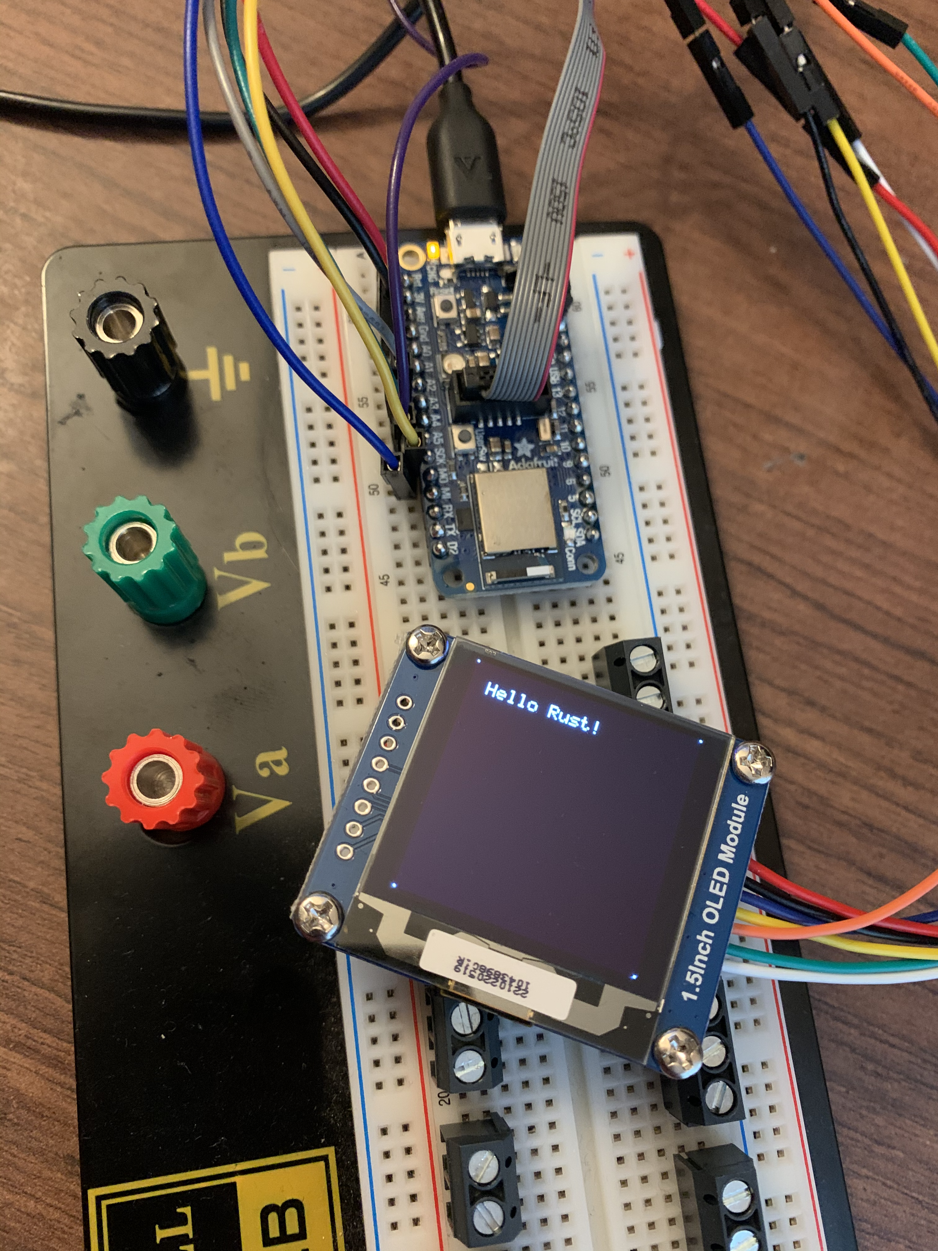
Real World Usage
In this example I’m using the Adafruit Feather nRF52840 Express board, together with the nrf52840-hal.
I’m connected to the board via the Segger J-Link Mini and use probe-run to flash the board.
If you do not own a J-Link device and don’t want to buy one, the nRF52840 DK has one already integrated. Check out my blog post for an introduction to it.
First, we need to grab our device peripherals:
|
|
To get a DelayMs trait implementation, we can use a Timer:
|
|
Next, we wire up all our SPI pins. The specific pins for your device of course might be different.
|
|
Since we are using the display-interface crate, we need to wrap our SPI implementation in its wrapper struct:
|
|
Finally, we can plug it into our display, reset and initialize it:
|
|
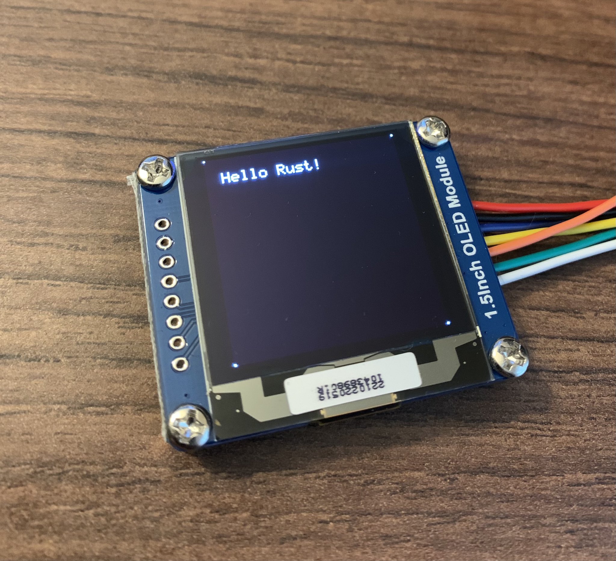
Time to render something! Also we should not forget to flush at the end. In this example we render one white pixel in every corner of the display as well as some text:
|
|
And there we go! Here is what gets rendered on the display:
At this point we have a working driver for our display. It doesn’t have many bells and whistles, but that can all be added later now that we understand how it works.
I hope you enjoyed this post as much as I did writing it! You can find the current version of the driver here.